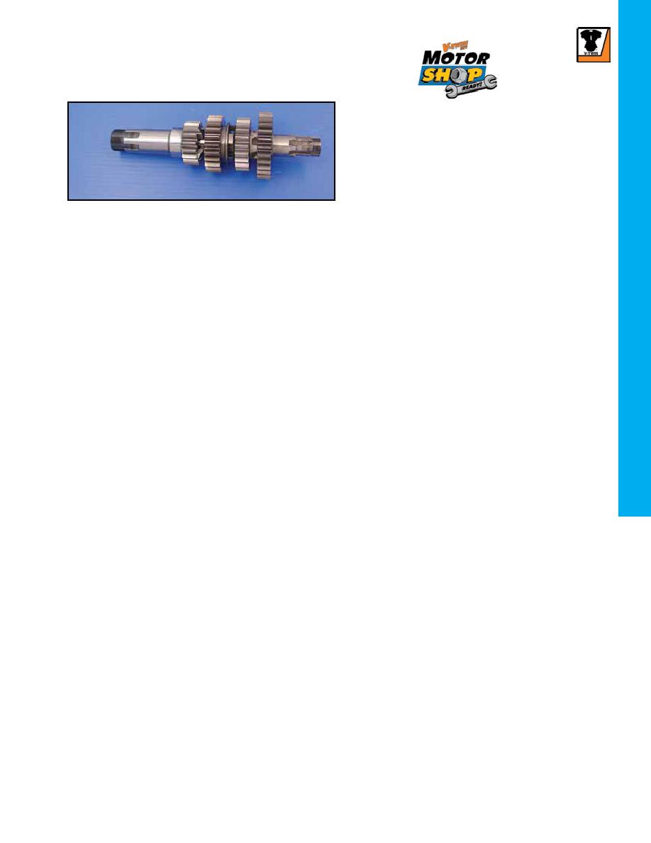
Cluster Assemblies. Each shaft is assembled with correct
thickness thrust washers and snap ring for proper gear clear-
ance. Also included is shaft end play washer assortment for
proper end play shimming during installation.
Mainshaft Assemblies
VT No.
All XL Transmission assemblies are bench tested for positive gear engagement and disengagement but it is always best for a
final check after unpacking transmission before being installed.
some early(Pre 1974) case this pin may have to be shortened or removed to allow cam plate to move freely. Failure to check
this will cause transmission to not completely shift through all gears. This should be checked first prior to assembly.
follower (I) from completing gearshifts. If hand pressure is released from shifter cam the gears will be drawn into complete
engagement and all inspection procedures will be performed incorrectly.
Shift transmission into first gear then check gear to dog Pocket Engagement. Correct engagement should be 25%.
Shift transmission into all other gears checking Pocket Engagement, which must be at least 50%.
Filing of lifter arms (Y+X) will produce changes in Pocket Engagement.
installed with Tang Down. For 1954-early 1984 models the mainshaft needle bearing will have to be installed. Temporarily install
access cover to crankcase with all transmission parts. Carefully align Cover Dowel Pins and with a rawhide mallet tap into posi-
tion and install four cap screws.
shift fork shaft will not go in to case. If shift fork shaft is forced into case damage or bending to shaft will happen causing shifter
roller finger to bind against shifter cam plate or shifter fork binging on shaft or with pawl carrier assembly.
bearing is .0006in-.0014in. If clearance is beyond specified limit a new race and bearings must be installed, and line lapped for
proper fit.
against lock ring in access cover. Move shaft back and forth and measure endplay while holding clutch gear in. If endplay is not
with specification (see chart) install thrust washer of suitable size.
and pull countershaft and measure endplay with dial indicator. If endplay is not within specification (see chart) install counter-
shaft washer of suitable size.
Stator must be installed on access door before above Endplay clearances can be established.
arm position changes when installing the transmission. Correct shaft to shifter pawl yoke engagement is important for proper
gear shifting. Install transmission and rotate countershaft slowly to check that the gear shift arm is engaged with shifter pawl. To
do so rotate shift lever, a noticeable resistance to movement indicates proper engagement.